Learn PCB Design of Arduino Pro Mini in Altium Designer 20.0 by following step by step tutorials of PCB designing
What you will learn
PCB Designing in Altium Designer Software.
You will learn all the basics of PCB Designing.
You will design your own arduino like board.
You will learn all the steps to design a PCB, from scratch to final product.
Work From Home as a Freelancer PCB Designer.
You will be able to design any customize PCB in Altium Designer after taking this course.
Make Money as a PCB Designer.
Description
Motivation:
Anyone who like to work in electronics or interested in designing the electronics product then learning a PCB design is essential for achieving this goal. By learning PCB design you can get a good earning job of Hardware design in different companies.
Altium Designer:
Selection of Tool for PCB design is very important. Altium Designer is a professional tool used in different companies to design all kind of boards, from very simple ones to motherboards or servers. It is a comprehensive and user friendly tool as compared to the other tools available in market.
What is in this Course:
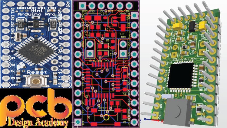
In this course we will design a customize PCB of Arduino pro mini by following step by step videos. We will start from the reference schematic of Arduino pro mini. We will redraw the schematic and then we will follow all the steps to make our own customize PCB. If you are new in PCB designing the by repeating these step by step tutorials you will be able to design a PCB. At the end of this course you will be able to design any customize PCB in Altium Designer. This course is to the point.
In Just 3 Hours you will learn how to:
1) Draw new Schematic.
2) Create new libraries.
3) Create Schematic Symbols and Footpints.
4) Placement of components in Design Area.
5) Routing of PCB.
6) Create Bill of Material (BOM).
7) Generate PCB Fabrication files (Gerber Files).
8) Generate PCB Production documentation (Assembly Drawings, Schematic in PDF format etc)
9) Create 3D Model of PCB
If you are interested, all the design documentation and Gerbers files produce in this course can be used to build your own PCB. You can source all the components from the DigiKey or Farnell and solder them by yourself.
Enjoy the Course and Best of Luck……..,
Target Audience:
- Beginners to intermediate skilled Altium Designer users
- Engineers migrating into Altium Designer
- Aspiring product entrepreneurs
- Students and researchers looking to design their custom PCB
- Anyone interested in designing PCB
Content