For Electrical Control Designers
What you will learn
You will navigate and familiarize yourself with the software’s user-friendly interface, tools, and functionalities
You will learn to create, edit, and manage electrical schematics with precision and clarity
You will learn the art of designing intricate panel layouts for various electrical projects
This course also covers a wide range of tools and features such as Circuit Builder, PLC module insertion, Report generation, Title blocks & Templates, and so on
Description
AutoCAD Electrical is the software of the AutoCAD suite which is intended to help control designers with the creation and modification of control systems. This software has extended features to automate control engineering tasks, such as building circuits, numbering wires, and creating bills.
For electrical engineers it is good for making circuit layout to power plant layout. This module includes drafting of electrical schematic diagrams, panel layouts, automatic report generation, PLC I/O drawing for spreadsheet, and so on.
This course is basically designed to assist the engineering students and the practicing designers. Keeping in view the varied requirements of the students, this course covers a wide range of tools and features such as schematic drawings, Circuit Builder, panel drawings, parametric and non-parametric PLC modules, stand-alone PLC I/O points, ladder diagrams, point-to-point wiring diagrams, report generation, creation of symbols, and so on. On the completion of this course, students will be able to create electrical drawings easily and effectively.
Salient Features of this Course:
- A tutorial based course consisting of 48 video lectures that are organized in a pedagogical sequence.
- Covers all important AutoCAD Electrical commands and tools.
- Step-by-step instructions to guide the users through the learning process.
- Self Evaluation Tests
- Certificate of Completion
Content
Introduction
Working with Project Manager
Working with Wires
Working with Ladders
Schematic Component Insertion
Schematic Component Editing
Connectors. Point to Point Wiring Diagrams, and Circuits
Panel Layouts
Reports Generation
PLC Modules
Terminals
Project and Drawing Properties, Title blocks and Templates
Creating Symbols and Using Miscellaneous Tools
An Honest Look at AutoCAD Electrical 2024: From a Design Veteran’s Perspective
I’ve been in the electrical engineering space long enough to remember when we literally had to hand-draw wire numbers and cross-references. If you missed one, the entire project fell apart. Moving into industry-standard tools like AutoCAD Electrical isn’t just about learning new software; it’s about changing your entire philosophy of design. This specific tutorial series for the 2024 version caught my eye because it doesn’t just treat the software like a “fancy digital pencil.” It treats it like a database management tool, which is exactly what modern Electrical Control Designers need.
The 2024 update brings some much-needed snappiness to the interface, but this course is where the real value lies. It bridges the gap between someone who knows how to draw a line and someone who can engineer a full-scale control system. What I appreciated most about this series is its focus on job-ready skills. It doesn’t waste hours on theory you’ll never use. Instead, it gets you into the hands-on labs quickly, forcing you to think about how components actually interact in a physical enclosure. If you’re tired of manually tracking Bill of Materials (BOM) or dreading wire-tagging updates, this course is your ticket to a much easier professional life.
Prerequisites for Success
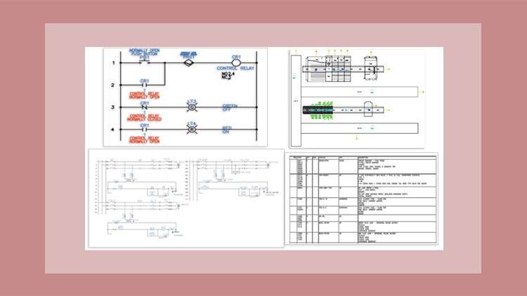
- A foundational understanding of electrical logic—you should know the difference between a Normally Open (NO) and Normally Closed (NC) contact before diving in.
- Basic computer literacy and a familiarity with the Windows environment.
- Access to a machine capable of running AutoCAD Electrical 2024 (check those system requirements, because 3D rendering and database management can be resource-heavy).
- While not strictly required, a basic understanding of 2D CAD concepts (like layers and blocks) will help you move through the beginner to advanced content much faster.
Mastering the Skills & Tools
This tutorial series is a deep dive into the “brain” of the software. You aren’t just placing symbols; you are building an intelligent system. Some of the core competencies you’ll walk away with include:
- Automated Wire Numbering & Tagging: Learning how to let the software handle the tedious numbering so you can focus on the actual logic.
- Intelligent PLC I/O Modules: You’ll learn how to insert PLC modules that actually communicate with your schematics, rather than just being static boxes on a page.
- Circuit Builder Mastery: One of the best parts of the course is using the Circuit Builder tool to dynamically generate motor control circuits based on wire size and load requirements.
- Database Management: Understanding how the Catalog Browser works to ensure that the parts you’re designing with actually exist in the real world.
- Cross-Referencing: Setting up real-time error checking so the software alerts you if you’ve assigned the same contact to two different relays.
Career Benefits & Job Roles
Investing time in this course is a massive catalyst for career growth. We are currently seeing a massive shortage of skilled control designers who actually understand the “Electrical” side of AutoCAD. Completing this series isn’t just about adding a line to your resume; it’s genuine certification prep for those looking to become Autodesk Certified Professionals.
The job-ready skills you gain here apply to several high-paying roles, including:
- Electrical Controls Engineer: Designing complex logic systems for manufacturing plants.
- Panel Designer/Draftsman: Specializing in the physical panel layouts and thermal management of enclosures.
- Systems Integrator: Helping different pieces of industrial machinery talk to one another through real-world projects and standardized schematics.
- Project Manager: Even if you aren’t drawing every day, knowing how Report generation and Title blocks work allows you to audit projects for accuracy and efficiency.
The Pros: Why This Course Stands Out
- Efficiency-First Mindset: The course emphasizes the “Project Manager” tool. It teaches you how to manage multiple drawings as a single cohesive unit, which is the hallmark of a professional workflow.
- Real-World Projects: You aren’t just drawing random shapes. The hands-on labs simulate actual industrial scenarios, like wiring a motor starter or configuring a PLC rack.
- Comprehensive Tool Coverage: It doesn’t skip the “boring” stuff. Learning how to properly set up Templates and Title blocks saves weeks of work in the long run, and this course gives those topics the respect they deserve.
The Cons: An Honest Critique
If I have one gripe, it’s that the course moves fast through the initial database configuration. AutoCAD Electrical relies heavily on its back-end SQL or Access databases for the catalog. For a complete novice, the setup of these libraries can feel a bit overwhelming if you don’t pause and re-watch those sections. It’s a “pro-level” tool, so the learning curve is naturally steep, and the course assumes you’re ready to put in the mental sweat to keep up.