Digital Photonics
What you will learn
Basic digital Photonics
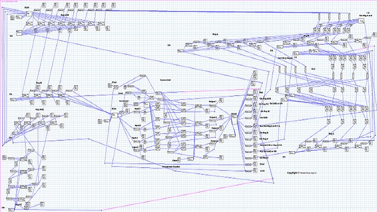
Basic Optical/Photonic CPU design
Micro-programming the Optical Control Unit
Basic Optical/Photonic Control Unit Design
Description
This course introduces the student to Digital Photonics. I have kept everything simple and to the point with a description of just a 4 bit optical CPU. Thus the registers with parallel load don’t use specialized circuitry for parallel load I just clock the clock line when needed in order to load values into a D type Register. This is naïve but the circuit works with slight nuances.
The goal of this course is to show the student a basic optical CPU to show it to work and to describe in detail the workings including a scalable and possibly reusable micro-programmable optical control unit.
The optical control unit uses a basic setup which is a mapping ROM attached to a presettable binary counter attached to a control ROM of which the outputs are programmed and map to various circuits for clocking or for setting a multiplexer or de-multiplexer etc. The component count including optical waveguides and pivot points is around 1000 components.
This course was a journey for me into optical circuit design with my own self designed Digital Photonic simulation software. I am sharing my first journey with the software which is a basic 4 bit optical CPU. The hobby software took about 6 long years to design and this circuit was used to test the software. I hope the course satisfies you curiosities of digital Photonics.
You should note that with this simulator I use proof of concept algorithms where a high intensity maps to a logic 1 and a low intensity maps to a logic 0. Thus at a high level the hardware algorithm can be shown to work. This is similar to Digital Electronics but in the optical domain.